Since the beginning of the project, a very simple circuit has been used to couple the SM24 sensor. It consisted of three 1 kΩ resistors: the one in middle serves as the termination shunt for the SM24, as indicated in the datasheet, and the other two resistors are used to limit the maximum current and protect the ADC. Using that solution, there are two things, which are bothering:
1. Because AINCOM was coupled with REFOUT (2.5 V) by software, using the level shift VBIAS function, the input signal had no zero mean. It is possible to compensate that by subtracting the mean of the input signal from the current signal value, but it was still not very elegant, besides some other disadvantages with spectral analysis.
2. The input signal had a very high 50 Hz noise.
Therefore, a better but still simple solution was used. Hereto, the middle 1 kΩ termination shunt was replaced by two 470 Ω resistors in series, a capacitor added parallel to the outlet of the SM24 in order to suppress high frequency noise and the REFOUT (2.5 V) connected with the middle of two 470 Ω resistors (see circuit figure). Now the input signal is symmetric, has a zero mean and the 50 Hz noise is greatly reduced, which leads to much better results.
In order to further reduce the noise, the build in low noise amplifier (PGA) was activated with a gain of 32 and the sample rate was set to 100 Hz. Using a 100 Hz sample rate instead of 400 Hz increases the noise free bits from 20 to 21, see data sheet. Using the PGA with a gain of 32 increases the input voltage by a factor of 32, therefore reduces the noise, but decreases the absolute measuring range by 5 bits. Since 16 bits noise free bits remain for measurement, the reduction of the noise is worth the reduction of the resolution.
Hardware
Old termination
The old termination of the SM24 by three 1 kΩ resistors: the one in the middle used as a termination shunt for the SM24 as listed in the data sheet, and the two other resistors in order to limit the maximal current and to protect the ADC.
New termination
The new termination of the SM24 by changing the middle 1 kΩ termination shunt by two 470 Ω resistors in series, a capacitor parallel to the outlet of the SM24 in order to suppress high frequency noise and REFOUT (2.5 V) connected to the middle of two 470 Ω resistors.
Results
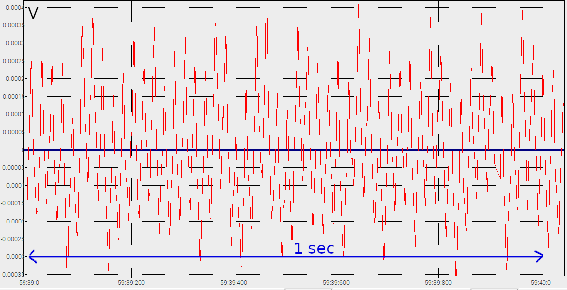
Old termination
At this figure, the current signal is already subtracted by the mean of the signal, therefore the output is quite symetrical. The 50 Hz noise is clearly perceptible (5 periods per 100 msec). The sample rate here is 400 Hz.
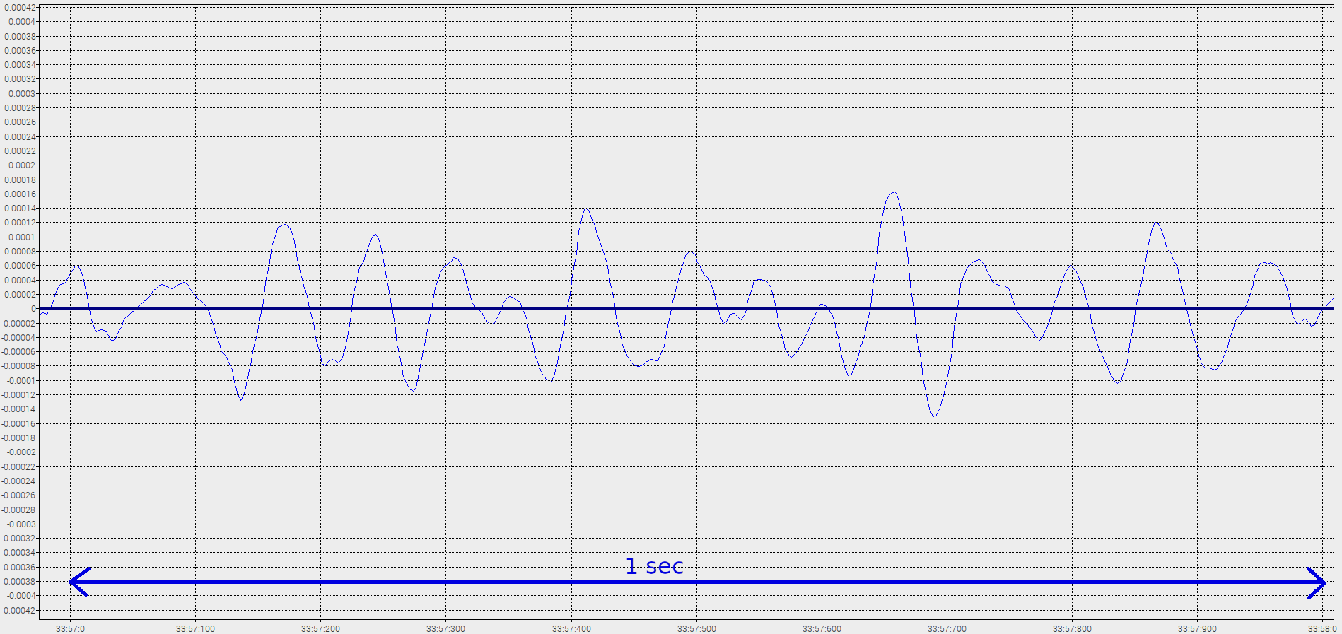
New termination
With the new termination, the signal already has a zero mean, nothing needs to be subtracted. Also the signal doesn’t have a perceptible 50 Hz noise anymore. The signal is much smoother and more clear. The sample rate here is 400 Hz.
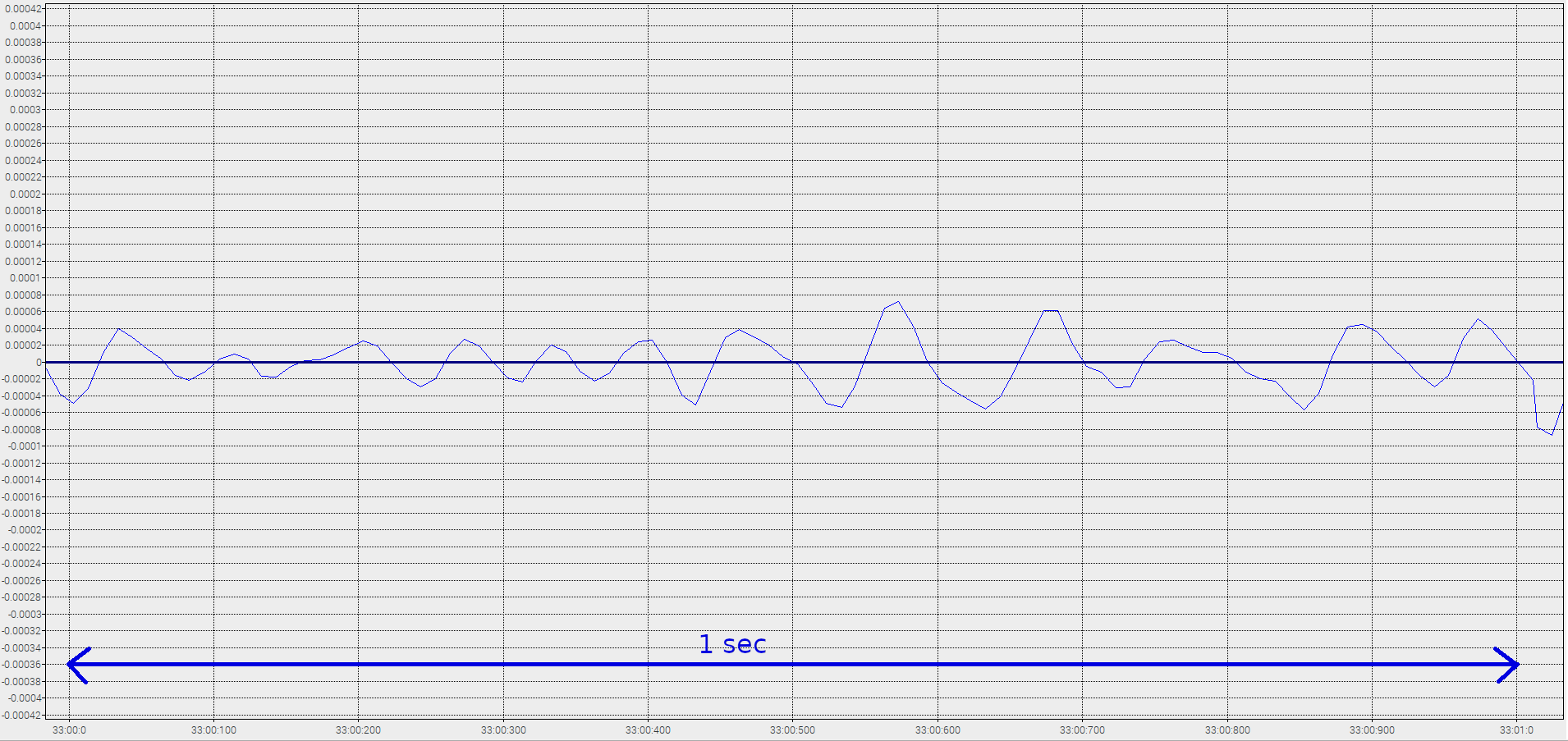
New setup
This figure shows the signal of the new setup, with:
Hi Jürgen, congratulations on the great project! I’m trying to implement the same thing as you, as I have the same ADC board and geophone and want to use the pi to measure velocity. I have an accelerometer calibrator, so I’ll be interested to check the reported velocities against the reference if I can get it working! On that, could you elaborate about how you connected the REFOUT of the chip?
Dear Derek!
The connection of the Refout Pin was a little difficult, as there was no connection for it on the pin header of the ADS1262 board.
Therefore, I had to solder a wire directly on the pins of the ADS1262 on the board.
Best regards,
Jürgen

24.05.2020 at 02:20
Hi Jürgen, congratulations on the great project! I’m trying to implement the same thing as you, as I have the same ADC board and geophone and want to use the pi to measure velocity. I have an accelerometer calibrator, so I’ll be interested to check the reported velocities against the reference if I can get it working! On that, could you elaborate about how you connected the REFOUT of the chip?
25.05.2020 at 10:54
Dear Derek!
The connection of the Refout Pin was a little difficult, as there was no connection for it on the pin header of the ADS1262 board.
Therefore, I had to solder a wire directly on the pins of the ADS1262 on the board.
Best regards,
Jürgen