
The ADS1115 from the last version had 16 bit resolution, which is a little few for a good seismometer. Most commercial seismometers use 24 bit resolution ADCs. Therefore, different ADCs have been looked for with a higher resolution, before much code is developed, which would have been to be rewritten because of a different ADC, exspecially if the ADC uses a different interface bus.
After considering a bunch of different ADCs, the winner was the ADS1262. The ADS1262 is an ultra-high resolution, low noise, 32-bit ADC with a build in amplifier and some more goodies. The ADS1262 is available as a breakout board from Protocentral, which is used here. The sensitivity of the ADS1262 is by a factor of more than 10,000 greater than the sensitivity of the ADS1115, which is a quantum leap in sensitivity.
Like anything men receive in live, it brings not only benefits, but also problems, which can be compared to the two faces of the Roman god Janus. Here the super high resolution theoretically offers the ability to measure voltages below 1nV, which is much below thermal and other noise. But on the other side, the noise disturbs now strongly our measurements and we loose several bits in resolution. If needed, this loss could be reduced by several optimizations like a printed circuit board instead of a breadboard, different power supplies, using digital SPI isolators and other things, but these thing would cost a lot of time, money and effort. Therefore, before we get lost in details, bits and bobs of only a single part of the project, we first concentrate on the completion of the seismometer. In any case, the sensitivity of the seismometer is with the ADS1262 better than before with the ADS1115.
If the two used analog inputs of the ADS1262, AIN0 and AINCOM, are short-circuit, the measured voltage should be 0. Instead, a peak-to-peak voltage noise of around 13-16 bits is measured, which leaves about 16 bits for noise-free resolution. For more information about noise-free resolution, effective number of bits (ENOB) and effective resolution see:
https://www.eetimes.com/document.asp?doc_id=1279085.
The current beta version V0.2 of the seismometer is based on the Raspberry Pi, the ADC ADS1262 and the SM-24 geophon and is still only a raw proof of concept, but it offers the potential for further optimizations.
The total list of the current hardware can be found at the Hardware page and a description of the current software is described at the Software page.
Hardware
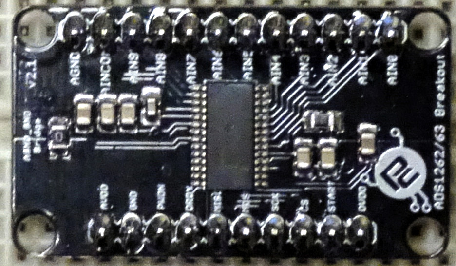
ADS1262
The ADS1262 is an ultra-high resolution, low noise, 32-bit ADC from Texas Instruments with a build in amplifier (PGA), SPI-bus, 10 input channels and some more goodies. The ADS1262 is available as a breakout board from Protocentral and is more difficult to program than the ADS1115.
The datasheet can be downloaded here:
http://www.ti.com/general/docs/lit/getliterature.tsp?genericPartNumber=ads1262&fileType=pdf.
The ADS1262 is available as a breakout board from Protocentral:
https://www.protocentral.com/analog-adc-boards/1005-protocentral-ads1262-32-bit-precision-adc-breakout-board-0642078949630.html.
Circuit diagram
The Raspberry Pi is connected with the ADS1262 by the GPIO pins. They deliver 5V, 3.3V, GND, MISO (SPI), MOSI (SPI), SCLK (SPI) and CS (SPI) signals.
For the connection between the SM-24 and the ADS1262 the same resistor circuit as with the ESP32 and ADS1115 is used. The 1kΩ resistor in the middle is a calibration resistor according to its data sheet in order to flatten the response curve. The other two 1kΩ resistors, leading to the ADS1262, are for current limiting, in case that the output voltage is larger than the maximum input voltage of the ADC. Even if the output voltage is 10V, which is much higher than the usual output of several mV, the current would be limited to 5mA, which doesn’t destroy the electrostatic discharge diodes (ESD) of the ADS1262 analog inputs.
Software
This software version is using the SPI bus in order to control the ADS1262.
The development of this version was much more complicated than the I²C version for the ADS1115. Several little problems had to be solved, e.g. the SPI mode of the ADS1262 is not 0 but 1. Of course, this information is listed in the datasheet on page 113 out of 133 pages, but you need to find and to recognize that too. This problem caused many headaches and blank despair, as nothing reasonable came out of the ADS1262 until the SPI mode was set to 1. Also the functionality, orders, registers and parameters are much higher than on the ADS1115. Last not least, the electrical coupling of the input channels are different to the ADS1115. The only friend in many hours of labor and measurement was the oscilloscope, which worked without complaining and contradiction, simply displaying the naked truth.
Nevertheless, the ADS1262 is an awesome and outstanding ADC and as soon as you get it running, you will get addicted to it (like a V8 engine 😉 ) and it’s sensitivity.
More information about the the current software version can be found at the Software page.
04.07.2019 at 09:46
I’m really interested with your project since like 3 months ago. And since then I learn a lot because this project is similar with my project that I’m doing right now. I’ve ever accessed the ADS1262 using microcontroller and it’s working perfectly. But now my project is slightly different. I’m trying to develop Raspberry Pi for the project using the ADS1262. And unfortunately I’m newbie in Raspberry Pi platform. I got difficulties to access the ADS1262 into the Raspberry Pi. Could you help me to figure it out? Or maybe you have another sample code that I really need to access it? Please respond this I almost desperate to figure this out. Thank you so much
27.07.2019 at 17:00
Dear Tsani!
The ADS1262 is different to most other ADCs for the Raspberry Pi for two main reasons. One reason is that the ADS1262 offers a much more sophisticated interface than most other ADCs. The other reason is that the higher resolution brings not only benefits, but also problems. You will face the second reason as soon as you get your ADS1262 up and running. There are many points to consider and I mentioned only a few very roughly here. In the next posts I will describe some of them more in detail.
Just like you I had a hard time to to get the ADS1262 running smoothly. Therefore, I described here exactly, what I did to solve these problems. If you have trouble with the Raspberry Pi and the ADS1262, you should follow the steps described and use the software library I published at GITHUB, see http://www.seismometer.info/software/ .
Good luck with the ADS1262 and best regards,
Jürgen
02.11.2019 at 15:32
This is a FANTASTIC website and source of information. Thank you SO much for taking the time to document and share your journey. THANK YOU!
04.11.2019 at 17:00
Dear W Turner!
Thanks for the nice words, it is indeed a lot of work to document and to format everything for the webpage.
Currently I would like to go ahead and finish the seismometer, but I am to busy.
Hopefully, I will finish the hardware and setup the seimometer into the soil until the end of the year.
Cheers,
Jürgen
10.12.2020 at 14:01
Superb !
I guess, to get a clean recording with such high resolution is a great challenge , one thing I can say ; You are a exceptional brain and I wish you the best !
Sincerely yours
10.12.2020 at 14:38
Dear Moshé!
Thank you for the encouraging words, all the best for the future during the corona restrictions.
Currently I am working on a little autonomous robot for schools and Universities, and I’ll soon create a website for this.
Cheers,
Jürgen