
The beta version V0.1 of the seismometer is based on the Raspberry Pi. The ADC is a ADS1115 analog-to-digital converter with a resolution of 16 bit. The geophon is the SM-24 geophon.
This version is still very simple and only a raw proof of concept. But it is able to visualize already some geophone data.
Hardware
Raspberry Pi
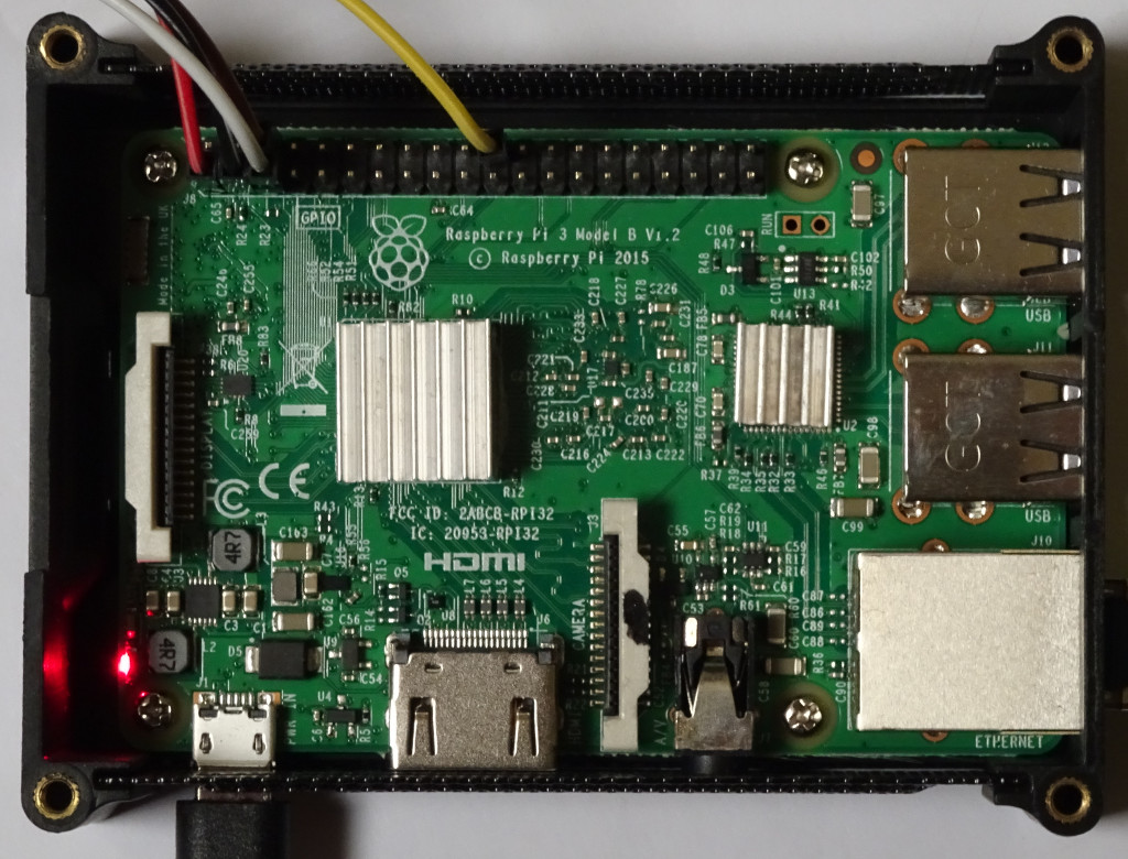
The Raspberry Pi model 3B is a tiny computer with a row of 40 GPIO (general-purpose input/output) pins. The ADC is connected with the GPIO pins, which provide power and reading and writing signals.
Power supply
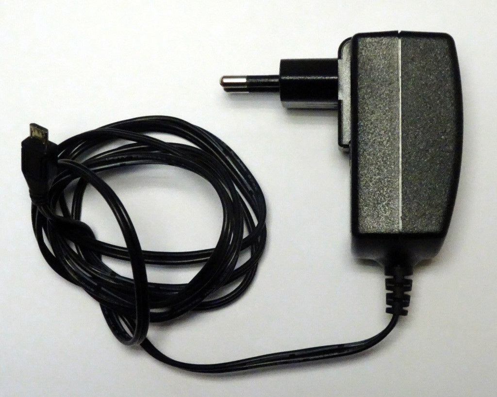
For the power supply of the Raspberry, the official 2.5A/5V power supply is used.

SSD
Since the data is saved in an SQL data base and the saved interval should be one month, a fast and sufficient large memory is needed. An micro SDHC card would be to small and to slow, so a 256 GB SSD from Samsung is used. No additional power supply is needed for an SSD, as it is powered over the USB interface. Furthermore, the SSD contains no rotating parts, which could hamper the measurements.
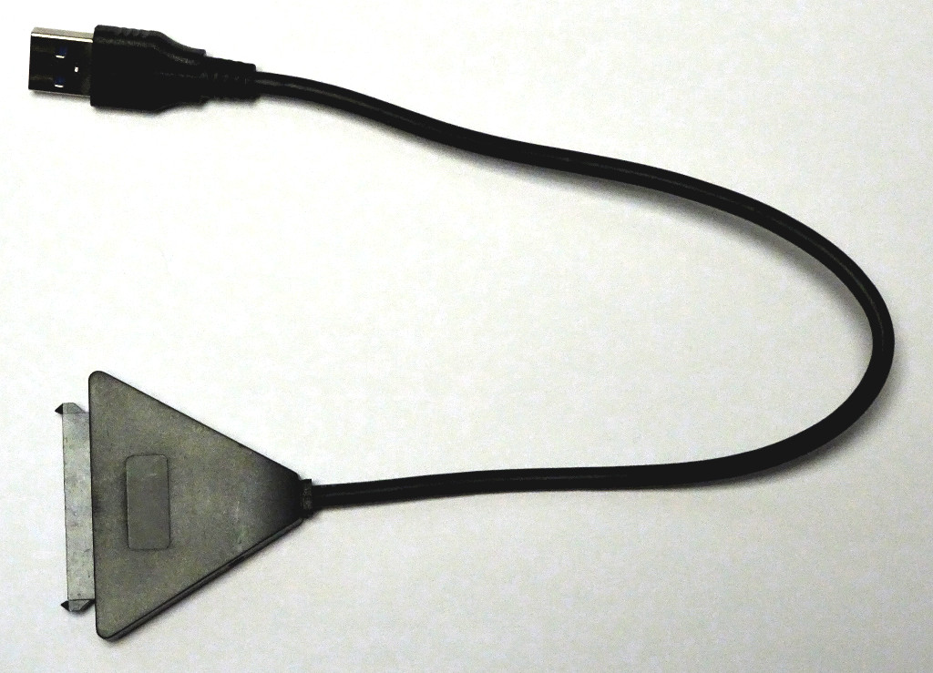
USB 3.0 to SATA converter
The SSD is connected to the Raspberry Pi via an USB 3.0 to SATA converter.
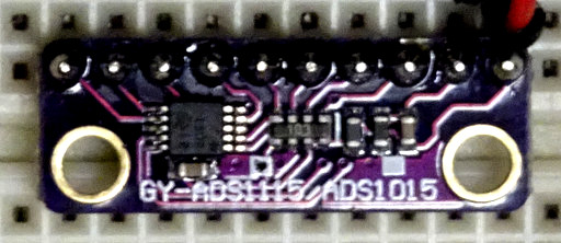
ADS1115
The ADS1115 from Texas Instruments is a 16 bit, 4 channel analog-to-digital converter. Here an Arduino shield version is used, which is easy to connect and to program.
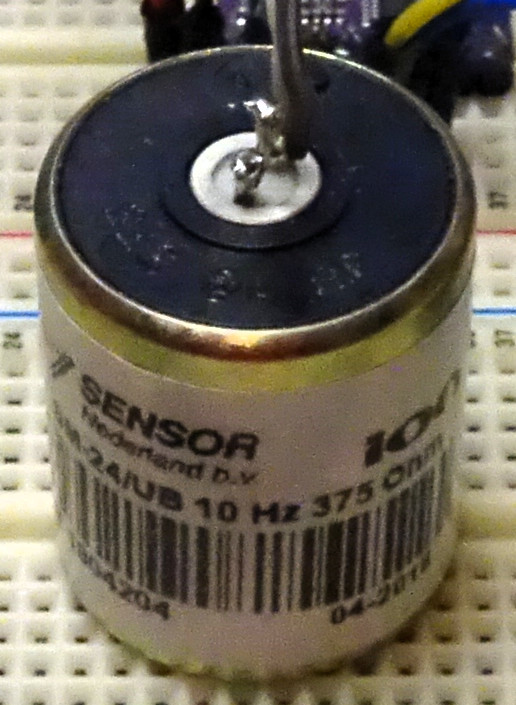
SM-24
The SM-24 is a low-distortion geophone, which offers very high performance in seismic exploration with an extended bandwidth from 10 Hz up to 240 Hz, allowing full bandwidth at 2 ms sampling, and with one of the lowest lifecycle cost of ownership in the industry, installed base of over 14 million worldwide.
Circuit diagram
The Raspberry Pi is connected with the ADS1115 by the GPIO pins. They deliver 3.3V VDD, GND, SCL (I²C) and SCA (I²C) signals.
For the connection between the SM-24 and the ADS1115 the same resistor circuit as with the ESP32 before is used. The 1kΩ resistor in the middle is a calibration resistor according to its data sheet in order to flatten the response curve. The other two 1kΩ resistors, leading to the ADS1115, are for current limiting, in case that the output voltage is larger than the maximum input voltage of the ADC. Even if the output voltage is 10V, which is much higher than the usual output of several mV, the current would be limited to 5mA, which doesn’t destroy the electrostatic discharge diodes (ESD) of the ADS1115 analog inputs.
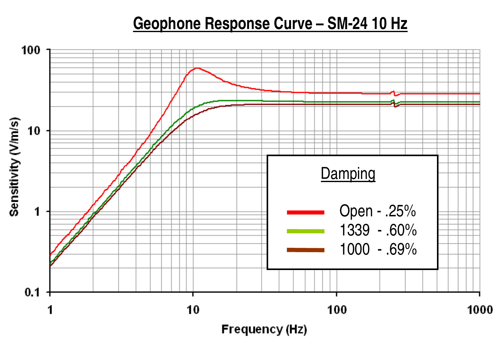
Frequency response
In order to get a flat frequency response, the output of the SM-24 is dampened with a 1kΩ resistor. The data sheet shows for the 1kΩ resistor (brown line) a quite flat response between 10 Hz and 1 kHz.
Software
This is software version V0.1 of the seismometer. It consists mainly of two parts: the ADS part as well as the control and visualization part. All software is written in PASCAL. The source code is Open Source, free available and is licensed under the GNU Lesser General Public License version 3 with linking exception, so you can use it in your own projects.
More information about the the current software version can be found at the Software page.
The source code can be downloaded from Github:

ADS1115_Unit
The file ads1115_unit.pas contains the source code for controlling the ADS1115. The ADS1115 is represented by the class T_ADS1115, which is defined and implemented in this file.
Class definition T_ADS1115
{ ####################################################################################### }
{ ## T_ADS1115                                                                         ## }
{ ####################################################################################### }
T_ADS1115 = Class (TObject)
Protected
    M_I2C_Address : U_Int_8;
    M_Gain :        U_Int_16;
    M_I2C_Handle :  CInt;
Public
    Constructor Create (F_I2C_Adress : U_Int_8 = ADS1115_ADDRESS; F_Gain : U_Int_16 = ADS1115_REGISTER_CONFIG_PGA_4_096V);
    Destructor Destroy; Override;
    Function I2C_Read_Buffer (F_Command : U_Int_8; F_Length : U_Int_8; F_P_Buffer : P_U_Int_8) : Integer;
    Function I2C_Write_Buffer (F_Command : U_Int_8; F_Length : U_Int_8; F_P_Buffer : P_U_Int_8) : Integer;
    Procedure Start_ALERT_RDY ();
    Procedure Stop_ALERT_RDY ();
    Procedure Start_ADC_Differential_0_1_Continuous_Conversion ();
    Function Get_Last_Conversion_Result () : Integer;
Published
End; { T_ADS1115 }
The class contains three member variables, which represent the state of the ADS1115.
M_I2C_Address contains the I²C address, which is $48 for this circuit board.
M_Gain represents the sensitivity range of the ADS1115 and is one of several constants offering a range from +/-0.256V to +/-4.096V.
M_I2C_Handle contains the file handle, as the ADS1115 is treated like a file from the operating system.
Constructor T_ADS1115.Create
{ --------------------------------------------------------------------------------------- }
Constructor T_ADS1115.Create (F_I2C_Adress : U_Int_8 = ADS1115_ADDRESS; F_Gain : U_Int_16 = ADS1115_REGISTER_CONFIG_PGA_4_096V);
{ Initialization of the object                                                            }
{ --------------------------------------------------------------------------------------- }
Begin { T_ADS1115.Create }
  Inherited Create ();

  { Initialize data }
  M_I2C_Address := F_I2C_Adress;
  M_Gain        := F_Gain;

  M_I2C_Handle := FpOpen ('/dev/i2c-1', O_RDWR);
  Sleep (100);
  If M_I2C_Handle < 0 Then
    Begin { then }
      { Error }
      ShowMessage ('Can not open I²C bus, Error:' + IntToStr (M_I2C_Handle));
      Halt;
    End; { then }

  { Connect as I2C slave }
  FpioCTL (M_I2C_Handle, ADS1115_I2C_SLAVE, Pointer (ADS1115_ADDRESS));
  Sleep (100);
End; { T_ADS1115.Create }
The constructor opens a file for controlling the ADS1115 and initializes the ADS1115 as an I²C slave.
Destructor T_ADS1115.Destroy
{ --------------------------------------------------------------------------------------- }
Destructor T_ADS1115.Destroy ();
{ Free data                                                                               }
{ --------------------------------------------------------------------------------------- }
Begin { T_ADS1115.Destroy }
  FpClose (M_I2C_Handle);

  Inherited Destroy;
End; { T_ADS1115.Destroy }
The destructor closes the file of the ADS1115 and releases the instance.
Function T_ADS1115.I2C_Read_Buffer
{ --------------------------------------------------------------------------------------- }
Function T_ADS1115.I2C_Read_Buffer (F_Command : U_Int_8; F_Length : U_Int_8; F_P_Buffer : P_U_Int_8) : Integer; Inline;
{ Return last conversion result                                                           }
{ --------------------------------------------------------------------------------------- }
Var
  I2C_Buffer_A : T_I2C_Buffer_A;
  Transaction :  T_I2C_Transaction;
  IOCTL_Data :   T_I2C_IOCTL_Data;

Begin { T_ADS1115.I2C_Read_Buffer }
  F_Length := Min (F_Length, ADS1115_I2C_BUFFER_MAX_SIZE);

  I2C_Buffer_A[0] := F_Length;

  If F_Length = ADS1115_I2C_BUFFER_MAX_SIZE Then
    Begin { then }
      Transaction := I2C_TRANSACTION_I2C_BLOCK_BROKEN;
    End { then }
  Else
    Begin { else }
      Transaction := I2C_TRANSACTION_I2C_BLOCK_DATA;
    End; { else }

  IOCTL_Data.Read_Write_Mode := I2C_READ_WRITE_MODE_READ;
  IOCTL_Data.Command         := F_Command;
  IOCTL_Data.Transaction     := Transaction;
  IOCTL_Data.P_Buffer        := @I2C_Buffer_A;

  If FpIOCtl (M_I2C_Handle, ADS1115_I2C_SMBUS, @IOCTL_Data) <> 0 Then
    Begin { then }
      Result := -1;
    End { then }
  Else
    Begin { else }
      Move (I2C_Buffer_A [1], F_P_Buffer^, I2C_Buffer_A [0]);
      Result := I2C_Buffer_A [0];
    End; { else }
End; { T_ADS1115.I2C_Read_Buffer }
I2C_Read_Buffer reads some bytes into a buffer from the I²C connection of the ADS1115. The input of the function consists of a command, the length and the address of the buffer.
Function T_ADS1115.I2C_Write_Buffer
{ --------------------------------------------------------------------------------------- }
Function T_ADS1115.I2C_Write_Buffer (F_Command : U_Int_8; F_Length : U_Int_8; F_P_Buffer : P_U_Int_8) : Integer; Inline;
{ Return last conversion result                                                           }
{ --------------------------------------------------------------------------------------- }
Var
  I2C_Buffer_A : T_I2C_Buffer_A;
  IOCTL_Data :   T_I2C_IOCTL_Data;

Begin { T_ADS1115.I2C_Write_Buffer }
  F_Length := Min (F_Length, ADS1115_I2C_BUFFER_MAX_SIZE);

  Move (F_P_Buffer^, I2C_Buffer_A [1], F_Length);
  I2C_Buffer_A[0] := F_Length;

  IOCTL_Data.Read_Write_Mode := I2C_READ_WRITE_MODE_WRITE;
  IOCTL_Data.Command         := F_Command;
  IOCTL_Data.Transaction     := I2C_TRANSACTION_I2C_BLOCK_BROKEN;
  IOCTL_Data.P_Buffer        := @I2C_Buffer_A;

  Result := FpIOCtl (M_I2C_Handle, ADS1115_I2C_SMBUS, @IOCTL_Data);
End; { T_ADS1115.I2C_Write_Buffer }
I2C_Write_Buffer writes some bytes to the I²C connection of the ADS1115. The input of the function consists of a command, the length and the address of the buffer.
Procedure T_ADS1115.Start_ALERT_RDY
{ --------------------------------------------------------------------------------------- }
Procedure T_ADS1115.Start_ALERT_RDY ();
{ Start ALERT/RDY interupt signal                                                         }
{ --------------------------------------------------------------------------------------- }
Var
  Buffer :       Packed Array [0 .. 9] Of U_Int_8;
  Result_Value : Integer;

Begin { T_ADS1115.Start_ALERT_RDY }
  { Turn on ALERT/RDY : Set MSB of Hi_thresh to 1 }
  Buffer[0]    := $8000 shr 8;
  Buffer[1]    := $8000 and $FF;
  Result_Value := I2C_Write_Buffer (ADS1115_REGISTER_POINTER_HIGH_THRESHOLD, 2, @Buffer [0]);

  If Result_Value < 0 Then
    Begin { then }
      ShowMessage ('Error writing to I²C (Set MSB of Hi_thresh to 1)');
      Halt;
    End; { then }

  { Turn on ALERT/RDY : Set MSB of Lo_thresh to 0 }
  Buffer[0]    := $0000 shr 8;
  Buffer[1]    := $0000 and $FF;
  Result_Value := I2C_Write_Buffer (ADS1115_REGISTER_POINTER_LOW_THRESHOLD, 2, @Buffer [0]);
  If Result_Value < 0 Then
    Begin { then }
      ShowMessage ('Error writing to I²C (Set MSB of Lo_thresh to 0)');
      Halt;
    End; { then }

  Sleep (100);
End; { T_ADS1115.Start_ALERT_RDY }
Start_ALERT_RDY initializes the ALERT_RDY pin of the ADS1115 to signal the end of a conversion. This signal can be used in order to generate an interrupt at the Raspberry Pi.
For more information take a look at the data sheet.
Procedure T_ADS1115.Stop_ALERT_RDY
{ --------------------------------------------------------------------------------------- }
Procedure T_ADS1115.Stop_ALERT_RDY ();
{ Stop ALERT/RDY interupt signal                                                          }
{ --------------------------------------------------------------------------------------- }
Var
  Buffer :       Packed Array [0 .. 9] Of U_Int_8;
  Result_Value : Integer;

Begin { T_ADS1115.Stop_ALERT_RDY }
  { Turn off ALERT/RDY : Set MSB of Hi_thresh to 0 }
  Buffer[0]    := $0000 shr 8;
  Buffer[1]    := $0000 and $FF;
  Result_Value := I2C_Write_Buffer (ADS1115_REGISTER_POINTER_HIGH_THRESHOLD, 2, @Buffer [0]);
  If Result_Value < 0 Then
    Begin { then }
      ShowMessage ('Error writing to I²C (Set MSB of Hi_thresh to 0)');
      Halt;
    End; { then }

  { Turn off ALERT/RDY : Set MSB of Lo_thresh to 1 }
  Buffer[0]    := $FFFF shr 8;
  Buffer[1]    := $FFFF and $FF;
  Result_Value := I2C_Write_Buffer (ADS1115_REGISTER_POINTER_LOW_THRESHOLD, 2, @Buffer [0]);
  If Result_Value < 0 Then
    Begin { then }
      ShowMessage ('Error writing to I²C (Set MSB of Lo_thresh to 1)');
      Halt;
    End; { then }
End; { T_ADS1115.Stop_ALERT_RDY }
Stop_ALERT_RDY turns of the signaling of the ALERT_RDY pin of the ADS1115.
For more information take a look at the data sheet.
Procedure T_ADS1115.Start_ADC_Differential_0_1_Continuous_Conversion
{ --------------------------------------------------------------------------------------- }
Procedure T_ADS1115.Start_ADC_Differential_0_1_Continuous_Conversion ();
{ Start continuous conversion mode                                                        }
{ --------------------------------------------------------------------------------------- }
Var
  Config :       U_Int_16;
  Buffer :       Packed Array [0 .. 9] Of U_Int_8;
  Result_Value : Integer;

Begin { T_ADS1115.Start_ADC_Differential_0_1_Continuous_Conversion }
  { Start ADC with continouos operation }
  Config :=
      ADS1115_REGISTER_CONFIG_OS_SINGLE or
      ADS1115_REGISTER_CONFIG_MUX_DIFF_0_1 or
      M_Gain or
      ADS1115_REGISTER_CONFIG_MODE_CONTINUOUS or
      ADS1115_REGISTER_CONFIG_DR_475SPS or
      ADS1115_REGISTER_CONFIG_CMODE_TRADITIONAL or
      ADS1115_REGISTER_CONFIG_CPOL_ACTVHIGH or
      ADS1115_REGISTER_CONFIG_CLAT_NONLATCH or
      ADS1115_REGISTER_CONFIG_CQUE_1CONV;

  Buffer[0]    := Config shr 8;
  Buffer[1]    := Config and $FF;
  Result_Value := I2C_Write_Buffer (ADS1115_REGISTER_POINTER_CONFIG, 2, @Buffer [0]);
  Sleep (100);
  Result_Value := I2C_Write_Buffer (ADS1115_REGISTER_POINTER_CONFIG, 2, @Buffer [0]);
  If Result_Value < 0 Then
    Begin { then }
      ShowMessage ('Error writing to I²C (Set config)');
      Halt;
    End; { then }

  { Turn on ALERT/RDY }
  Start_ALERT_RDY ();
End; { T_ADS1115.Start_ADC_Differential_0_1_Continuous_Conversion }
Start_ADC_Differential_0_1_Continuous_Conversion turns on the continuous conversation mode of the ADS1115. At the end of the procedure, the ADS1115 will continuously convert analog values into a digital value, which can be read by the function below.
For more information take a look at the data sheet.
Function T_ADS1115.Get_Last_Conversion_Result
{ --------------------------------------------------------------------------------------- }
Function T_ADS1115.Get_Last_Conversion_Result () : Integer;
{ Return last conversion result                                                           }
{ --------------------------------------------------------------------------------------- }
Var
  Result_Value : Integer;
  Buffer :       Packed Array [0 .. 9] Of U_Int_8;

Begin { T_ADS1115.Get_Last_Conversion_Result }
  Result_Value := I2C_Read_Buffer (ADS1115_REGISTER_POINTER_CONVERT, 2, @Buffer);
  If Result_Value <> 2 Then
    Begin { then }
      Result_Value := I2C_Read_Buffer (ADS1115_REGISTER_POINTER_CONVERT, 2, @Buffer);
      If Result_Value <> 2 Then
        Begin { then }
          Buffer[0] := 0;
          Buffer[1] := 0;
        End; { then }
    End; { then }

  Result := Int_16 ((Buffer [0] shl 8) or (Buffer [1]));
End; { T_ADS1115.Get_Last_Conversion_Result }
Get_Last_Conversion_Result returns the value of the last conversation of the ADS1115.
For more information take a look at the data sheet.
Main_Unit
The files main_unit.pas and main_unit.frm contain the source code for the main application form. The form contains a chart, which displays the results. This unit controls two threads: one thread for reading the sensor data, represented by the class T_Timer_Thread, and a second thread, which is the main thread of the program represented by class TMain_F, for displaying the data at the chart.
Class definition T_Timer_Thread
{ ####################################################################################### }
{ ## T_Timer_Thread                                                                    ## }
{ ####################################################################################### }
T_Timer_Thread = Class (TThread)
Protected
    Procedure Execute; Override;
Public
    M_X_A :       Array [0 .. ARRAY_SIZE - 1] Of TDateTime;
    M_Y_A :       Array [0 .. ARRAY_SIZE - 1] Of Integer;
    M_A_Input_P : integer;
    M_ADS1115 :   T_ADS1115;
    M_X :         Integer;
    Constructor Create (F_Suspended : Boolean);
    Destructor Destroy; Override;
End; { T_Timer_Thread }
T_Timer_Thread is a thread class for reading the sensor data from the ADS1115. The sensor data is read in polled operation and saved in a ring buffer. The frequency of the polling loop is around 500 Hz (2 ms).
The class contains member variables for the sensor data in form of arrays, for the current index of the arrays, for the ADS1115 class, and for a total data counter.
Constructor T_Timer_Thread.Create
{ --------------------------------------------------------------------------------------- }
Constructor T_Timer_Thread.Create (F_Suspended : Boolean);
{ Create timer thread                                                                     }
{ --------------------------------------------------------------------------------------- }
Begin { T_Timer_Thread.Create }
  FreeOnTerminate := FALSE;

  M_ADS1115 := T_ADS1115.Create (ADS1115_ADDRESS, ADS1115_REGISTER_CONFIG_PGA_0_256V);
  M_ADS1115.Start_ADC_Differential_0_1_Continuous_Conversion ();

  M_X         := 0;
  M_A_Input_P := 0;

  Inherited Create (F_Suspended);
End; { T_Timer_Thread.Create }
The constructor creates the ADS1115 object, starts the continuous operation mode of the ADS1115 and initializes the index and the total counter. At the end the thread is created as suspended, id est it must be started by calling Execute.
Destructor T_Timer_Thread.Destroy
{ --------------------------------------------------------------------------------------- }
Destructor T_Timer_Thread.Destroy ();
{ Free data                                                                               }
{ --------------------------------------------------------------------------------------- }
Begin { T_Timer_Thread.Destroy }
  M_ADS1115.Stop_ALERT_RDY ();
  M_ADS1115.Free;

  Inherited Destroy;
End; { T_Timer_Thread.Destroy }
The destructor stops the continuous operation mode of the ADS1115 and frees the ADS1115 object.
Procedure T_Timer_Thread.Execute
{ --------------------------------------------------------------------------------------- }
Procedure T_Timer_Thread.Execute;
{ Execute thread                                                                          }
{ --------------------------------------------------------------------------------------- }
Begin { T_Timer_Thread.Execute }
  While (Terminated = FALSE) Do
    Begin { While }
      Sleep (2);

      M_X_A[M_A_Input_P] := M_X;
      M_Y_A[M_A_Input_P] := M_ADS1115.Get_Last_Conversion_Result ();

      Inc (M_X);
      Inc (M_A_Input_P);
      If M_A_Input_P >= ARRAY_SIZE Then
        Begin { then }
          M_A_Input_P := 0;
        End; { then }
    End; { While }
End; { T_Timer_Thread.Execute }
The Execute procedure contains the thread loop. The sensor data is read in polled operation with a sleep command in order not to stress the CPU to much. All data is saved in a ring buffer. The frequency of the loop is around 500 Hz (2 ms sleep).
Class definition TMain_F
{ ####################################################################################### }
{ ## TMain_F                                                                           ## }
{ ####################################################################################### }
TMain_F = Class (TForm)
    ADC_C :           TChart;
    ConstantLine :    TConstantLine;
    Chart_S :         TLineSeries;
    Close_B :         TButton;
    Label3 :          TLabel;
    Output_NPS_E :    TEdit;
    Output_EPanel1 :  TPanel;
    Chart_T :         TTimer;
    Procedure Chart_TTimer (Sender : TObject);
    Procedure Close_BClick (Sender : TObject);
    Procedure FormCreate (Sender : TObject);
    Procedure FormShow (Sender : TObject);
Protected
    M_Timer_Thread : T_Timer_Thread;
    M_A_Output_0_P : integer;
    M_A_Output_1_P : integer;
    M_Start_Time :   TDateTime;
    M_End_Time :     TDateTime;
Public
End; { TMain_F }
TMain_F is the class for the main form of the application. The form contains a chart, which displays the sensor data. At the bottom if the form is a close button and a display field, which shows the throughput of the sensor data in number of measurements per second (=frequency of the polling loop).
The class contains different member variables for the components on the form.
Procedure TMain_F.FormCreate
{ --------------------------------------------------------------------------------------- }
Procedure TMain_F.FormCreate (Sender : TObject);
{ Create main from                                                                        }
{ --------------------------------------------------------------------------------------- }
Begin { TMain_F.FormCreate }
  Chart_S.Clear;
  ADC_C.Extent.YMax := CHART_START_Y;
  ADC_C.Extent.YMin := -CHART_START_Y;

  M_Timer_Thread := T_Timer_Thread.Create (TRUE);
End; { TMain_F.FormCreate }
FormCreate clears and initializes the chart and creates the thread object for reading the sensor data.
Procedure TMain_F.FormShow
{ --------------------------------------------------------------------------------------- }
Procedure TMain_F.FormShow (Sender : TObject);
{ Show main form                                                                          }
{ --------------------------------------------------------------------------------------- }
Begin { TMain_F.FormShow }
  M_A_Output_0_P := 0;

  Chart_T.Interval := CHART_INTERVAL;
  Chart_T.Enabled  := TRUE;

  M_Timer_Thread.Start;

  M_Start_Time := Now;
  M_End_Time   := Now;
End; { TMain_F.FormShow }
FormShow starts the thread object and initializes some variables.
Procedure TMain_F.Close_BClick
{ --------------------------------------------------------------------------------------- }
Procedure TMain_F.Close_BClick (Sender : TObject);
{ Close button pressed                                                                    }
{ --------------------------------------------------------------------------------------- }
Begin { TMain_F.Close_BClick }
  Chart_T.Enabled := FALSE;

  M_Timer_Thread.Terminate;
  Sleep (100);
  M_Timer_Thread.Free;

  Close;
End; { TMain_F.Close_BClick }
Close_BClick is executed when the user presses the button or the escape key and simply closes the form and the program.
Procedure TMain_F.Chart_TTimer
{ --------------------------------------------------------------------------------------- }
Procedure TMain_F.Chart_TTimer (Sender : TObject);
{ Repaint chart                                                                           }
{ --------------------------------------------------------------------------------------- }
Var
  I : Integer;

Begin { TMain_F.Chart_TTimer }
  Chart_S.BeginUpdate;

  M_A_Output_1_P := M_Timer_Thread.M_A_Input_P - 1;
  For I          := M_A_Output_0_P To M_A_Output_1_P Do
    Begin { For }
      Chart_S.AddXY (M_Timer_Thread.M_X_A [I], M_Timer_Thread.M_Y_A [I]);
    End; { For }
  Chart_S.EndUpdate;

  ADC_C.Extent.XMin := M_Timer_Thread.M_X - CHART_SIZE;
  ADC_C.Extent.XMax := M_Timer_Thread.M_X;

  M_End_Time := Now;

  Output_NPS_E.Text    := FormatFloat ('#.##0.000', Double (M_A_Output_1_P - M_A_Output_0_P) / (Double (MilliSecondSpan (M_Start_Time, M_End_Time)) / 1000));
  Application.ProcessMessages;

  M_Start_Time   := M_End_Time;
  M_A_Output_0_P := M_A_Output_1_P;
End; { TMain_F.Chart_TTimer }
Chart_TTimer contains the code for one iteration of the timer loop. It is called about once a second. After turning of the auto-update functionality of the chart (Chart_S.BeginUpdate), the chart is filled with all data of the ring buffer since the last iteration and the auto-update functionality of the chart is turned on (Chart_S.EndUpdate). Then the visible section of the x-axis is moved to the right, the throughput of the sensor data in number of measurements per second is calculated and displayed at the bottom line of the form and some variables updated with the current values.
Visualization of sensor data

The first chart
This beta version of the seismometer can display first results of the geophone in a little chart.
This is just the beginning of our journey. Many tasks are ahead of us: Precise reading in time, saving and sorting data in a database, higher resolution of the ADC, spectral analysis of the data, 3D measurements, generating live data visualization for the Internet, connecting to international networks…, so let’s go ahead.
11.04.2020 at 14:46
Hi Juergen,
I wondered if you thought of implementing a low cost GPS receiver such Ublox Neo-6M to the system for accurate time taghing the samples using 1 PPS signal?
And if one stores data without your SQL database would that eliminate the need for a bulky power thirsty external hard disk by using a microsd storaage medium?
Regards,
Alireza
14.04.2020 at 08:35
Dear Alireza!
Thanks for your comment.
Concerning the time accuracy, I think it is sufficient to use an internet time server.
Also with a GPS receiver, you have to make sure you can receive the signal all the time.
But if you want to have more precice time values, the GPS card you mentioned might be a good choice.
The SSD doesn’t consume so much power and it fits nicely into the casing, but my main reason was, that I wanted to use a big database and for that the SSD is the better choice over an SDHC-Card.
With best regards,
Jürgen